July 22, 2015 – Hey did you know that Universal Instruments regularly embraces new technologies to fuel innovation and improve time to market for our customer-focused solutions? A recent example of this is our new 3D printer!
Back in the good ol’ days of 2014, we foresaw the opportunity to utilize 3D printing as a way to prototype our flexible tooling solutions and get a useable product into our customers’ hands much faster (among other uses). So, we purchased a Fortus 400MC 3D Printer, which produces full-form, three-dimensional objects by extruding melted materials from a coil to form layers. Then, once a layer is complete, a bed is lowered by one layer thickness at a time and the next layer is extruded (think of a hot glue gun in action). This technology is called Fused Deposition Modeling (FDM), which uses plastic materials such as ABS, Static Dissipative ABS, Polycarbonate, Nylon and Ultem to “print” objects. The typical processing time to 3D print an object ranges from 20 minutes to 24 hours, and is volume-dependent.
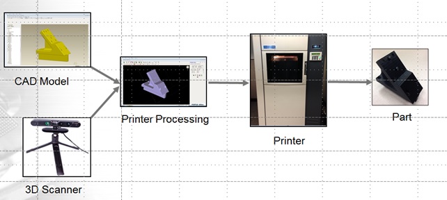
How does 3D Printing Work?
A 3D CAD model or 3D digital file from a scanner is processed and sliced into hundreds of thousands of layers. These layers may be as thin as 15um (think width of a strand of human hair or even smaller, object dependent). When this prepared file is uploaded to the 3D printer, the printer recreates the object layer by layer, as a series of two-dimensional images, growing the part.
Here’s a video of our Fortus400 in action:
[icon icon=”film” size=”small” style=”simple” shape=”inherit”][/icon] Video: FDM Process
3D printing is not only really cool technology, it’s useful too. Here’s what we did with it. But first, a brief introduction to DIMMs (Dual In-Line Memory Modules). . .
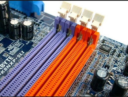
To accommodate memory in devices such as personal computers, workstations and servers, electronics manufacturers install Dual Inline Memory Modules (DIMMs) connectors on printed circuit boards (PCBs). The DIMMs consist of a series of dynamic random-access memory integrated circuit devices.
The current type of DIMM technology, in use since 2007, is based on DDR3 memory devices. With DDR3 now reaching its limits in a world that demands higher performance and increased bandwidth, a new generation of DIMM has arrived, based on DDR4 memory devices. DDR4 DIMMs deliver higher performance, improved data integrity and lower power consumption. Because of this increased capability, the electronics industry in now in transition from DDR3 to DDR4 DIMMs.
DDR4 DIMM connectors present a unique assembly challenges to manufacturers for the following reasons. First the spacing of the pins is much tighter. The older style DDR3 DIMM connectors typically have 240 pins, while the newer-style DDR4 DIMM connectors now have 288 – a 20% increase in the number of pins that needs to fit into the same amount of space! Secondly, manufacturers have increased the height and thickness of DDR4 DIMM connectors to make signal routing easier, and to accommodate more signal layers with the goal of driving more functionality into the same amount of space. Lastly, based on these complex factors, it has become very difficult to accurately place DDR4 DIMM connectors by hand. Hand insertion often results in bending of the pins due to the uneven force being applied by the operator’s hand when placing the connector on the PCB. Operators are also unable to consistently inspect all pins on the DDR4 DIMM connector. Hand placement ultimately results in much lower accuracy, leading to lower throughput and yield; hence the significant trend towards automated placement of DDR4 DIMM connectors.
Now that you know what the issues are with DDR4s, here’s what we did to help our customer automate their DDR4 DIMM connector process:
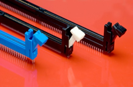
One of our large customers, a global EMS company, came to us because they were having issues with their DDR4 DIMM connectors. Each of the printed circuit boards on their line required up to 24 DDR4 DIMMs, which they were placing by hand (and based upon what you learned above, you know this practices has issues.) The DDR4 DIMMs were being supplied to them from their vendor in vacuum-formed bulk packaging (see Exhibit A). This type of packaging does not allow for a repeatable pick position when the connectors need to be fed into an SMT machine for placement on the PCB. It is also one of the main reasons that manufacturers still populate these types of connectors. Without an appropriate packaging solution, this process could not be automated.
Using our NEW 3D printer technology, we conceptualized and created a new packaging solution for the DDR4 DIMM connectors called a Matrix Tray Feeder (See Exhibit B). This feeder was printed on our Fortus 400MC using a special type of static-dissipative plastic material that prevents electro-static discharge events. The Matrix Tray Feeder allowed the DDR4 DIMMs to be consistently fed into the SMT placement machine, resulting in automatic and accurate placement. This feeder was part of a solution that enabled the transition from a manual to an automated process for their DDDR4 DIMM connectors (See Exhibit C). The final solution, which also required creation of a new gripper and adaptor, as well as modifications to the SMT machine’s imaging system, helped to increase our customer’s first-pass yield from 85 to 99% – a 14% improvement!
Want to learn more about DIMM connectors? Stay tuned for an upcoming post: “The Transition from DDR3 to DDR4s in the Electronics Industry”
Exhibit A – DDR4 DIMM Connectors in vacuum formed bulk packaging
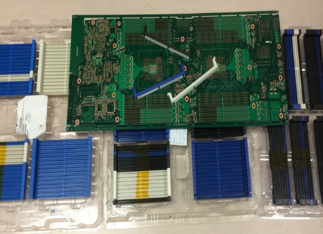
Exhibit B – 3D Printed Matrix Tray Feeder
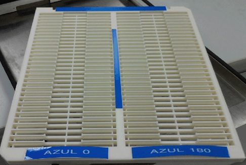
Exhibit C – Final board with 24 DDR4 DIMM Connectors

Click below to see a video of our DDR4 DIMM connector solution in action:
[icon icon=”film” size=”small” style=”simple” shape=”inherit”][/icon] Video: DIMM Connector
So how does 3D Printing Technology play into this?
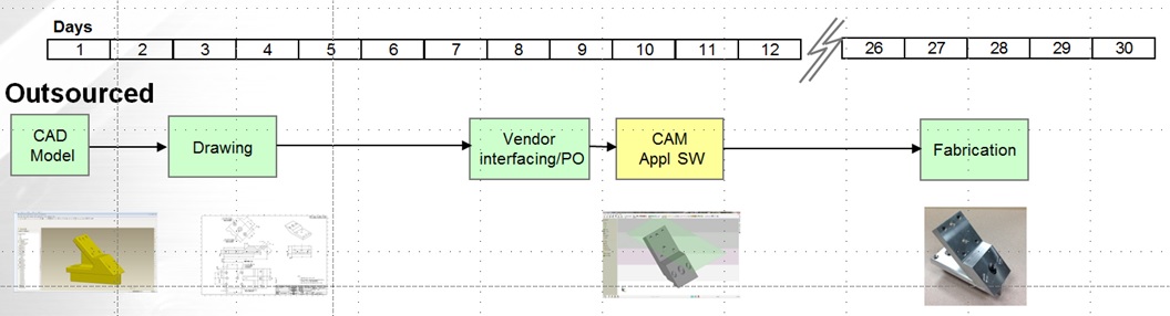
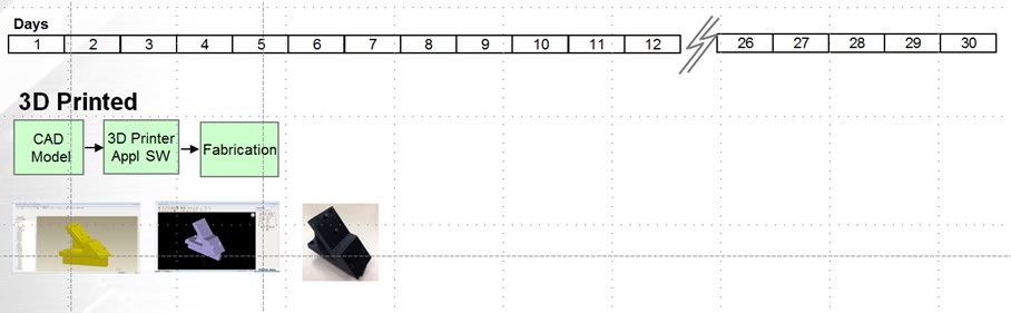
After designing the Matrix Tray Feeder using AutoCAD software, (a commercial software application for computer-aided design (CAD), we were able to quickly produce this solution in less than 1 week and with just 12 hours of printing time on our 3D printer, compared to more than 3 weeks’ time if we had sent this out for off-site (outsourced) production. And did I mention this was also done at half the cost? Yes, that’s right… faster and cheaper.
(Prototyping using an Outsourced Model)
(Prototyping using 3D Printer Technology)
In addition to rapid prototyping, we are also using our 3D printing technology for functional concept modeling and in-house manufacturing tooling design. We will continue to look for ways to use this cool technology to deliver faster and cheaper solutions for our customers’ needs now and in the future as we embrace change to innovate – a core part of our company culture!
Do you have a tooling solution challenge that you think might benefit from quick prototyping on our 3D printer like the DDR4 DIMM connector solution we delivered? If so, tell us all about it, and we’ll put our technology and expertise to work for you today. Contact:
Rick Buchanan, Senior Applications Engineer
UIC Tooling Solutions Group
E-mail: buchanan@uic.com
Office: +1 607-779-5038